- English
- French
- German
- Portuguese
- Spanish
- Russian
- Japanese
- Korean
- Arabic
- Greek
- German
- Turkish
- Italian
- Danish
- Romanian
- Indonesian
- Czech
- Afrikaans
- Swedish
- Polish
- Basque
- Catalan
- Esperanto
- Hindi
- Lao
- Albanian
- Amharic
- Armenian
- Azerbaijani
- Belarusian
- Bengali
- Bosnian
- Bulgarian
- Cebuano
- Chichewa
- Corsican
- Croatian
- Dutch
- Estonian
- Filipino
- Finnish
- Frisian
- Galician
- Georgian
- Gujarati
- Haitian
- Hausa
- Hawaiian
- Hebrew
- Hmong
- Hungarian
- Icelandic
- Igbo
- Javanese
- Kannada
- Kazakh
- Khmer
- Kurdish
- Kyrgyz
- Latin
- Latvian
- Lithuanian
- Luxembou..
- Macedonian
- Malagasy
- Malay
- Malayalam
- Maltese
- Maori
- Marathi
- Mongolian
- Burmese
- Nepali
- Norwegian
- Pashto
- Persian
- Punjabi
- Serbian
- Sesotho
- Sinhala
- Slovak
- Slovenian
- Somali
- Samoan
- Scots Gaelic
- Shona
- Sindhi
- Sundanese
- Swahili
- Tajik
- Tamil
- Telugu
- Thai
- Ukrainian
- Urdu
- Uzbek
- Vietnamese
- Welsh
- Xhosa
- Yiddish
- Yoruba
- Zulu
What is the difference between an actuator and a motorized valve?
When specifying flow control equipment for industrial pipelines, procurement professionals often encounter the terms "actuator" and "motorized valve" used interchangeably, creating confusion during vendor negotiations and technical reviews. The distinction matters significantly. An actuator is the driving mechanism that converts electrical, pneumatic, or hydraulic energy into rotational or linear motion, while a motorized valve is a complete assembly combining both the valve body and the integrated actuator as a single unit. In butterfly valve applications, the butterfly valve motorized actuator specifically refers to the electric motor-gear system mounted on the valve stem, delivering the precise torque needed to rotate the disc through 90 degrees. Understanding this difference helps distributors, contractors, and OEM clients select components that align with retrofit needs, installation constraints, and automation requirements.
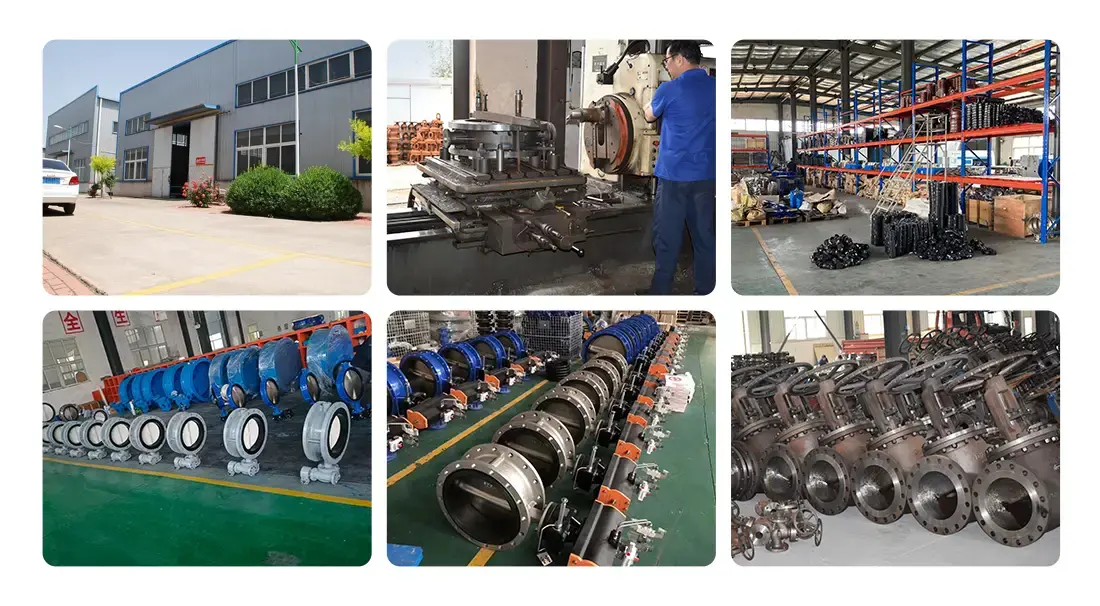
Understanding the Basics: What Is an Actuator and What Is a Motorized Valve?
Actuators: The Driving Force Behind Valve Movement
Actuators take energy and turn it into mechanical motion. They provide the force needed to open, stop, or change the position of valves. Electric motors are the most common type used in industry because they work well in a variety of environments and can be easily integrated with control systems. These gadgets have an engine, gearbox, control electronics, and a mounting link that meets standards like ISO 5211. Pneumatic actuators respond quickly, but they need a system for storing compressed air. Hydraulic actuators, on the other hand, can handle high pressures and produce a lot of force.
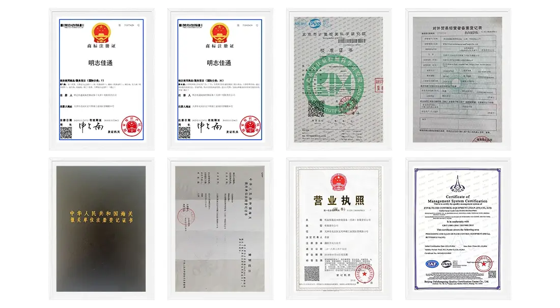
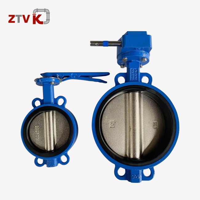
There are standard square or round drive connections between the actuator and the valve stem in butterfly valve installations. The gearbox slows down the motor while increasing the torque. This makes it possible for large-diameter valves to work reliably even when there is differential pressure. Modern electric actuators have a position input, which lets them work with remote control systems to watch and change things in real time.
Motorized Valves: Integrated Automation Solutions
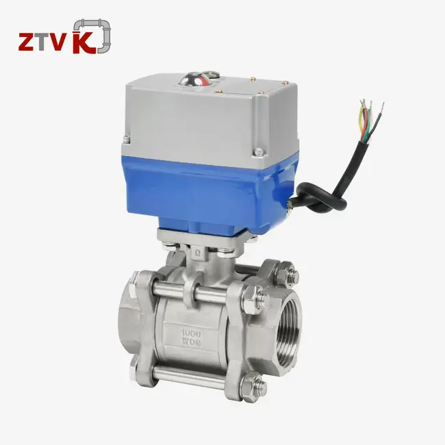
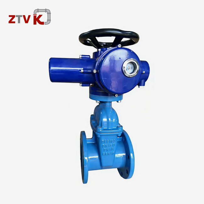
The actuator and valve body are both part of a motorized valve, which comes pre-assembled and tested at the plant. This unified method gets rid of problems with field alignment and cuts down on installation time, which makes it a good choice for projects that need to be done quickly. The actuator mounting, stem coupling, and seal compatibility are all improved during production to make sure they work reliably from the time they are put into service for decades.
Motorized butterfly valves come with safe housings that are rated for different environments (IP67 for outdoor installations, explosion-proof standards for dangerous zones) and are ready to be connected to power sources and control signals. The unified design makes buying easier by putting all of the vendor control and guarantee coverage in one place.
Choosing Between Components and Complete Assemblies
Distributors who work with a wide range of customers usually keep both stand-alone motors and full motorized valves in stock. Standalone actuators give customers options when they want to keep their current valve stock on hand or need unique designs. Full motorized valve assemblies make buying easier and make sure that everything works together, which is especially helpful when workers are under a lot of time pressure to meet project targets. Which arrangement gives the best value depends on how the customer works.
How Do Actuators and Motorized Valves Work? A Functional Comparison?
Electric Actuator Operation in Butterfly Valve Applications
Electric actuators use AC motors (usually 220V or 380V for industrial uses) that are connected to multiple stages of reduction gears. The motor shaft turns quickly and with little force when it is turned on. The gearbox, which is usually a worm-and-wheel or planetary arrangement, slows down the rotational speed while raising the drive shaft's output power by the same amount. Through an ISO 5211 interface, this shaft is linked to the butterfly valve stem. The motor's rotation causes the disc to move.
Signals from automation systems are read by control circuitry inside the butterfly valve motorized actuator housing. Actuators that turn on and off respond to simple open-close directions through limit switches that stop motor activity at the ends of their ranges. Modulating actuators have positioners that can handle 4-20 m. Analog signals are used to keep changing the position of the valve to keep the flow rates accurate. Electronics inside the machine keep an eye on torque, temperature, and cycle counts, sending diagnostic information using protocols like Modbus RTU or Profibus.
The torque needs to change a lot depending on the size of the valve and the working pressure. For example, a DN600 butterfly valve under PN16 pressure might need 800 Nm of unseating torque, which means it needs an actuator with a rating of at least 1,040 Nm (using a 1.3x safety factor). When actuators are too small, the gears wear out quickly, and the motors burn out, and when they are too big, they cost more to buy and use more energy.
Motorized Valve Functionality and Control Integration
Motorized valves make operation easier by putting the electronics for the actuators in a single control box. Factory wiring links the motor, position sensors, and terminal blocks using a standard design. This lowers the chance of mistakes during installation in the field. During assembly, the valve disc, stem seals, and actuator mounting are all matched to ensure the best torque transfer and leak-tight performance.
These units have weatherproof cord glands that let you connect power and control data. Control rooms are always told where things are by feedback mechanisms like potentiometers, proximity switches, or encoder-based systems. During commissioning, techs use internal adjustment screws or digital interfaces to set the failsafe behavior, journey limits, and speed settings.
Smart diagnostics are built into more advanced motorized valves so that they can keep track of working factors over time. Data on cycle numbers, stall events, and temperature changes are available to maintenance teams. This lets them plan predictive maintenance that stops unexpected downtime. This information is useful in petrochemical plants where broken valves can cause expensive process interruptions.
Key Differences Between an Actuator and a Motorized Valve in Procurement Considerations
Cost Analysis and Lifecycle Value
Standalone actuators are often 20–30% cheaper than motorized valve assemblies that do the same job, which makes them appealing to distributors who have to keep an eye on margin pressures. However, owners have to find valves separately, make sure they work with each other, and oversee the quality of fitting in order to save money at first. There are hidden costs when problems with field alignment slow down starting or when warranty claims get disputed over whether failures were caused by valve or actuator flaws.
Motorized valves cost more, but their total cost of ownership is known. Factory testing confirms performance under rated conditions, which lowers the risk of commissioning. Single-source warranties stop vendors from blaming each other, and standard spare parts make planning long-term maintenance easier. For workers who are working on multiple jobs at the same time, this predictability makes the initial investment worthwhile.
When existing manual butterfly valves meet the requirements but need to be automated, retrofit applications prefer standalone actuators. Distributors that work with industries that need a lot of upkeep keep a supply of popular actuator types that can be used with existing valves. This lets upgrades happen quickly without having to change the pipeline.
Installation and Maintenance Requirements
To properly install solo actuators, including butterfly valve motorized actuator systems, you need to know how to work with mechanics to line up the drive shafts, check the torque gearbox, and seal the mounting connections. An incorrect coupling can cause eccentric loading, which speeds up bearing wear and leads to seal failure before it should. Contractors need to make sure they have enough skilled workers and plan for longer installation times in their project schedules.
Motorized valves come with the right fitting frames, gaskets, and bolts for their combination. Installation is as simple as connecting power lines, bolting flanges together, and checking the movement limits. These are jobs that general techs can do, not experts. This makes things easier, which saves money on labor and speeds up the project's completion, which is especially helpful when installing multiple valves at the same time.
Different configurations have slightly different maintenance procedures. Gearbox lubrication, electrical link check, and limit switch calibration are the main parts of actuator service. Maintenance for valves includes sealing the stem, replacing the disc seal, and checking the body. When used together in motorized assemblies, coordinated maintenance schedules increase uptime by taking care of both parts during planned shutdowns instead of doing them separately.
How to Choose Between a Motorized Actuator and a Motorized Valve for Butterfly Valve Applications?
Evaluating Operational Requirements and Environmental Constraints
Doing the right pick starts with figuring out the torque. Engineers need to know the disc width, the friction coefficient of the seat material (EPDM, NBR, PTFE, or Viton), and the highest differential pressure the valve will be exposed to. 25–30% safety margins are used to account for seals that are getting old and possible pressure surges. ZTVK helps wholesalers and contractors with technical issues by figuring out exactly how much power is needed based on project standards and suggesting actuators with the right rating.
Ratings for enclosures and material decisions are based on the environment. For locations near the coast, actuators need to have marine-grade coatings and housings made of stainless steel (C4/C5-M corrosion protection) so they can handle salt spray. In mines or cement plants with a lot of dust, IP66 grades or higher are needed to keep particles out. Extreme temperatures can change the lubricant that is used and the stability of electronics. For example, installations in the desert may need interior heaters to keep condensation from forming, while uses in the Arctic need cold-rated grease formulas.
The architecture of the control system affects the choice between simple on/off actuators and more complex modulating actuators. Chemical dosing in water treatment plants often needs precise flow control, which is why positioner-equipped actuators that accept analog signals are preferred. Fire safety systems use high-speed motors with fail-safe spring return devices to make sure doors close quickly.
Supplier Evaluation and Quality Assurance
Procurement managers look at what suppliers can do that goes beyond what the product specifications say. ISO 9001 certification shows that you handle quality in an organized way, and ISO 14001 certification shows that you care about the environment. Objective performance proof comes from third-party testing records, such as power validation reports, endurance cycle data, and ingress protection verification. ZTVK keeps detailed test records for every production batch. This makes it possible to track products and be sure they are always the same.
Delivery dependability affects both project schedules and managing inventory. Distributors that serve area markets need sellers who have a lot of stock on hand and can fill orders quickly. Over 2,000 standard units (DN50–DN600) are kept by ZTVK in stores in Tianjin. This means that orders can be delivered 3–7 days after they are confirmed. Non-standard setups with unique materials or connection standards ship between 15 and 25 days. For an extra fee, you can get them faster in 7 to 10 days.
Technical help is what sets good providers apart from average ones. Having access to application experts who can look over specs, suggest configurations, and fix problems with installation is very helpful. ZTVK offers CAD drawings, 3D models for coordinating designs, and installation tutorial videos that cut down on the time needed for commissioning and the number of mistakes that happen in the field, including support for butterfly valve motorized actuator selection and application.
Conclusion
Telling the difference between actuators and motorized valves makes buying choices easier and gets the most out of automation investments. Actuators let you easily add new features to valves that are already in your inventory, and motorized valves make new installations easier by integrating design and making commissioning simpler. The choice is based on the limitations of the project, the needs of operations, and the overall cost over its lifetime. It is easy to use, accurate, and current. Automation systems can easily connect butterfly valve motorized actuators to water treatment, HVAC, and industrial process uses. Long-term reliability and operational success are guaranteed by looking at torque requirements, environmental factors, and supplier capabilities.
FAQ
1. Can Manual Butterfly Valves Be Converted to Motorized Operation?
Standard ISO 5211 mounting connections on manual butterfly valves let electric actuators connect, making automation improvements easy. For conversion, you need to check the stem's dimensions, make sure it can handle torque, and make sure the valve body can handle the frequency of automated cycling. For older valves to handle more rounds, the stem seal may need to be replaced.
2. What Advantages Do Electric Actuators Offer Compared to Pneumatic Versions?
Electric motors don't need infrastructure for compressed air, which lowers the cost of installation in places that don't have pneumatic systems. They allow for precise positioning in flow modulation applications and connect directly to control networks that use electricity. Pneumatic actuators have shorter stroke times that make them good for emergency shutdowns, but they need air pumps and pipes to distribute the air.
3. How Do I Calculate the Required Actuator Torque for My Application?
When figuring out torque, you need to know the size of the valve, the highest differential pressure, the friction coefficient of the seat material, and the safety limit. The method takes the disc size and multiplies it by the differential pressure and a friction factor that is based on the properties of the seat material. Using a 1.3x safety factor takes into account changes in pressure and seal wear over time. To make sure the right choice is made, manufacturers like ZTVK offer sizing tools and application tech help.
Partner with ZTVK for Reliable Butterfly Valve Motorized Actuator Solutions.
Industrial valve wholesalers, contractors, and OEM clients looking for reliable butterfly valve motorized actuators and full motorized valve systems can get all of their automation needs met by ZTVK. Our factory in Tianjin keeps a large stock of DN50–DN2000 configurations with electric operation, flanged connections that meet ISO 5211 and PN10/PN16 standards, and body materials such as ductile iron, WCB, SS304, and SS316. Our production processes are ISO 9001 certified to ensure consistent quality, and we are close to Tianjin Port, which makes international shipping quick. Standard models can be delivered in 3–7 days.
We offer OEM branding, custom material specs, and expert advice to make sure that your project needs are met exactly. For application-specific size suggestions, low bulk prices for distributors, and full product documentation, please email our engineering team at ktec86961886@163.com.
References
1. Hutchison, J. W. (2019). Industrial Valve Selection and Specification: A Practical Guide for Engineers and Procurement Professionals. Technical Publishing International.
2. Miller, R. D., & Chen, L. (2021). Actuator Technology in Process Automation: Design, Application, and Maintenance. Engineering Press.
3. Standards Committee on Industrial Valves (2020). ISO 5211: Industrial Valves - Part-Turn Actuator Attachments - Specifications and Testing. International Organization for Standardization.
4. Pearson, M. A. (2018). Butterfly Valve Engineering: Principles, Applications, and Performance Optimization. Fluid Control Systems Journal, 45(3), 127-156.
5. Thompson, K., & Rodriguez, F. (2022). Electric Actuators in Industrial Applications: Selection Criteria and Lifecycle Management. Automation Technology Review, 18(2), 78-94.
6. Wagner, S. (2020). Valve Automation for Water and Wastewater Systems: Best Practices for Specification and Installation. Municipal Engineering Publications.
Send us your valve requirements and our team will provide professional solutions and fast quotations.
RELATED INDUSTRY KNOWLEDGE
