- English
- French
- German
- Portuguese
- Spanish
- Russian
- Japanese
- Korean
- Arabic
- Greek
- German
- Turkish
- Italian
- Danish
- Romanian
- Indonesian
- Czech
- Afrikaans
- Swedish
- Polish
- Basque
- Catalan
- Esperanto
- Hindi
- Lao
- Albanian
- Amharic
- Armenian
- Azerbaijani
- Belarusian
- Bengali
- Bosnian
- Bulgarian
- Cebuano
- Chichewa
- Corsican
- Croatian
- Dutch
- Estonian
- Filipino
- Finnish
- Frisian
- Galician
- Georgian
- Gujarati
- Haitian
- Hausa
- Hawaiian
- Hebrew
- Hmong
- Hungarian
- Icelandic
- Igbo
- Javanese
- Kannada
- Kazakh
- Khmer
- Kurdish
- Kyrgyz
- Latin
- Latvian
- Lithuanian
- Luxembou..
- Macedonian
- Malagasy
- Malay
- Malayalam
- Maltese
- Maori
- Marathi
- Mongolian
- Burmese
- Nepali
- Norwegian
- Pashto
- Persian
- Punjabi
- Serbian
- Sesotho
- Sinhala
- Slovak
- Slovenian
- Somali
- Samoan
- Scots Gaelic
- Shona
- Sindhi
- Sundanese
- Swahili
- Tajik
- Tamil
- Telugu
- Thai
- Ukrainian
- Urdu
- Uzbek
- Vietnamese
- Welsh
- Xhosa
- Yiddish
- Yoruba
- Zulu
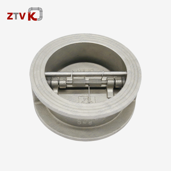
How to adjust the level gauge of a 4 inch flanged check valve?
A simple process is used to adjust the level gauge on a 4-inch flanged check valve. This allows for accurate tracking of the valve disc position and flow conditions. The level gauge, which is usually attached to the outside of the valve body, needs to be calibrated on a regular basis to show the correct interior conditions. First, release all the pressure in the system. Then, loosen the bolts that hold the gauge in place. Using the manufacturer's markings, recalibrate the indicator to the position of the disc. Finally, fix all the connections again while checking that the zero-point is still straight. This guide answers a practical question for buying managers, engineers, and dealers who choose and keep industrial valves in systems for water supply, HVAC, petrochemicals, and cities. Correctly calibrating level gauges has a direct effect on how well they work, keeps expensive breaks from happening, and increases the life of equipment in harsh industrial settings. Procurement workers can make better choices about which valves to buy, which suppliers to work with, and how to do maintenance in a way that meets international standards and meets project deadlines when they understand the adjustment process.

Understanding the Level Gauge in a 4-Inch Flanged Check Valve
What is a level gauge, and why does it matter?
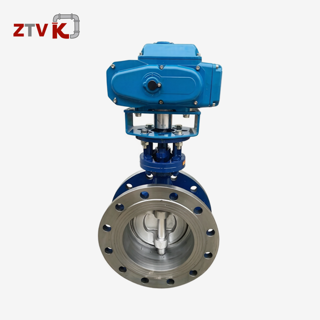
A level gauge, which can be seen or touched, keeps an eye on where the check valve disc is while it's working. The gauge in a DN100 (or 4-inch flanged check valve) gives instantaneous input on whether the valve is still open, closed, or partly engaged. This knowledge is very important for people who are in charge of complicated pipe systems because it helps them keep the flow going and stop backflow.
The gauge is connected to the valve assembly by a stem that goes through the internal disc device and connects to it. The disc opens when fluid moves forward, and the gauge point or indicator moves in the same way. The disc shuts, and the gauge goes back to zero when the movement stops or changes direction. This simple but effective design lets maintenance teams check the performance of the valves without taking the whole unit apart. This saves time during normal checks.
Common Issues from Incorrect Gauge Settings
When gauges aren't calibrated correctly, they cause a number of practical problems that lower the effectiveness of the system. If the indicators aren't lined up right, they might say the valve is still open when it's actually closed, which could cause operators to make bad choices about the state of the system. This can lead to backflow that wasn't planned, water hammer, or damage to the pump from rotating backwards. When valves don't fit properly, there are often changes in pressure. If the gauge isn't accurate, the problem goes unnoticed until it shows up in more important ways.
Over time, material suitability also affects how accurate the scale is. Valves made of cast iron or WCB carbon steel, such as 4-inch flanged check valves, work reliably within certain temperature ranges. For example, common types like the HC41X work reliably between -20°C and 200°C. But thermal expansion and contraction can change the accuracy of a gauge, especially in situations where temperatures change quickly. ANSI and DIN standards set measurement limits that help makers make gauges that don't drift. However, field conditions always bring changes that mean the gauges need to be adjusted from time to time.
Diagnosing Problems: Why Adjust the Level Gauge?
Key Indicators Signalling Adjustment Needs
There are a few signs that your level gauge needs to be recalibrated. When pressure numbers aren't the same across the system, it's often because the valve discs aren't where the gauge says they are. If workers see that the scale says the valve is fully open but the pressure drops, which means flow is being limited, they need to look into it right away. Noises like rattling or vibrations that don't make sense during operation could mean that the disc is moving back and forth between places. The gauge should show this, but it doesn't always when the tuning has changed.
Leakage around the valve body or overflow detection through pipes further downstream proves functional issues that a precise gauge would have helped find earlier. When these signs show up, the first step in diagnosing is to compare the gauge reading to how the valve actually acts. This can be done by looking at it visually through access holes or by correlating it with data from a flow meter.
Root Causes Behind Gauge Drift
Misalignment of the gauge is often caused by mistakes during installation. Technicians may not zero the gauge correctly before pressurising the system during the initial setup. This can cause a shift that lasts the entire life of the valve. Over a long period of time, parts naturally wear out. This is especially true in high-cycle situations where the disc opens and closes thousands of times a year. Friction and material wear cause the mechanical connection between the disc and the gauge to gradually become less accurate and play.
These problems are made worse by environmental factors. Vibrations from nearby machines can loosen the hardware that holds the gauge in place, and acidic atmospheres can damage the gauge case and connection points. Inspections that are planned ahead of time find these issues early, so maintenance teams can fix the gauges before the loss of accuracy affects process control. Proactive methods stress visual checks every three months and functional tests once a year, which increase valves' useful life and improve their performance in a wide range of industry settings.
Step-By-Step Guide to Adjusting the Level Gauge of a 4-Inch Flanged Check Valve
Preparation and Safety Protocols
When working with pressure systems, safety is still the most important thing. Using upstream and downstream block valves to completely isolate the system is the first step in the adjustment process. Lock-out-tag-out methods keep high-pressure fluids from leaking out while repair is being done. This keeps people safe. Depressurization has to happen slowly so that there aren't any big changes in pressure that could damage valve parts or pipe links.
Before you start working, get the tools you'll need. For flange bolts, you'll need wrenches of the right size (usually 13mm to 19mm for Class 125/150 flanges), a torque wrench for putting things back together, calibration reference papers from the maker, and safety glasses and gloves for your own protection. It's smart to have a spare set of gaskets on hand, since flanged connections that have been disturbed sometimes need new closing materials to keep them leak-tight.
Accessing and Adjusting the Gauge Assembly
Locate the gauge fixing piece on the outside of the valve body of the 4-inch flanged check valve after the system is disconnected and no longer under pressure. The gauge body is usually held in place by a threaded link or a bolted flange. Carefully loosen these connections, making sure to keep track of the original position and direction for when you put them back together. Some types have a lock nut that stops the adjustment from happening when the machine is in regular use. The nut has to be loosened before the calibration can be changed.
When you open the access cover, you can see the internal chain that links the gauge to the valve disc stem. The system for adjusting usually has either a threaded rod that changes the linkage's useful length or a slotted connection that lets the indicator arm be moved. Place the valve disc manually so that it is fully closed. Depending on the form of the valve, this may require opening the valve bonnet or using an external tool. Once you're sure the disc is closed, line up the gauge indicator with the zero mark on the face of the dial.
Post-Adjustment Verification
Put the gauge case and attachment tools back together, and if necessary, replace the gaskets to keep the environmental seal. Take out the lockout/tagout devices and slowly repressurise the system while keeping an eye out for leaks around any connections that have been messed with. As the system pressure rises, watch how the gauge reacts to make sure it accurately shows how the valve works in real-life flow circumstances.
Run the valve through a number of open-and-close cycles to make sure it works. When the flow stops, the gauge should always go back to zero and move to the right place when the flow starts again. Write down the date and results of the calibration in the maintenance log so that you can use them as a starting point for future comparisons. This information backs up predictive maintenance programs and helps find trends that could point to deeper system problems that need more attention.
Comparing Level Gauge Adjustments Across Valve Types and Materials
Design Variations and Their Impact
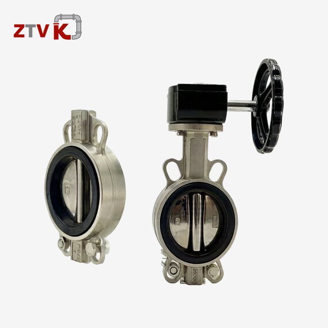
The process for adjusting different types of check valves is a little different. A hinged disc on a swing check valve moves away from the flow path. Usually, gauges on the top of the valve keep track of the disc angle through a direct mechanical link. The linkage line stays pretty simple in these patterns, so they are easy to change. When you put a wafer-style check valve between two flanges, it doesn't go past the width of the pipe. These valves may have smaller gauge assemblies that need special tools to reach and change.
Material Considerations for Different Environments
Valve body material has a big impact on how long a gauge lasts and how often it needs to be adjusted. When used in corrosive settings, stainless steel valves (ASTM A351 CF8M) keep their shape over long periods of time, which helps keep gauge reading. Because it is more resistant to rusting, rust and flaking don't form, which could otherwise bind linkage parts or bend mounting surfaces. When used with harsh chemicals, seawater, or acidic condensates, where component life directly affects total cost of ownership, these valves are worth the extra money they cost at first.
Pressure Classes and Temperature Effects
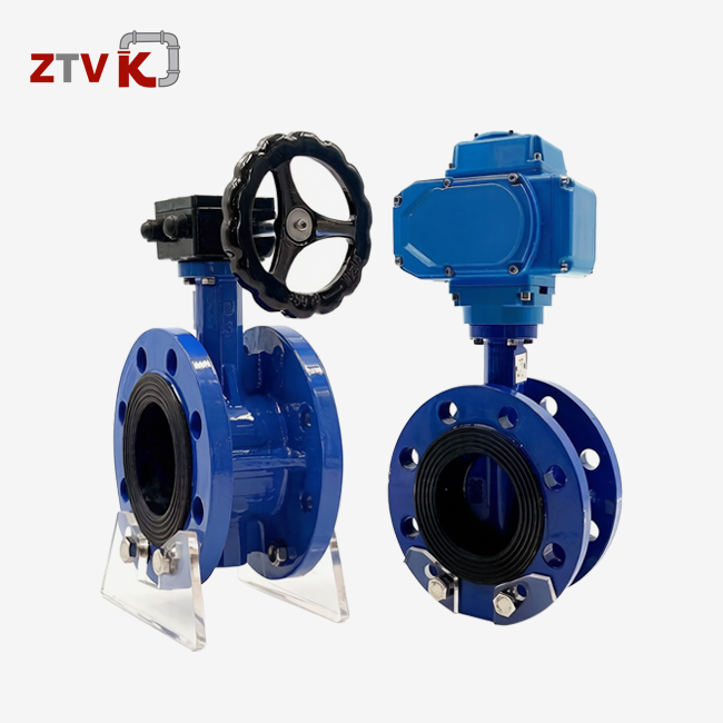
Even though cast iron and WCB carbon steel valves (4-inch flanged check valves) are cheaper, they need more care to be environmentally friendly. Models like the HC41X Flange Sound-Damping Check Valve are made of cast iron or WCB and can handle pressures up to 1.6 MPa in sizes DN40 to DN300. The temperature range of -20°C to 200°C includes most of the water supply, HVAC, and city uses where these materials work best. But because cast iron breaks easily when it gets too hot or cold and carbon steel rusts easily, gauge systems made of these materials may need to be checked and adjusted more often than those made of stainless steel.
Conclusion
The right way to set the level gauge makes sure that flanged check valves work well and can be monitored for the whole time they are in use. Even though the process of adjusting is simple, it needs to be done with care and following safety rules, organized steps, and checks that make sure the accuracy works in real-world situations. Procurement pros and technical teams can make valves more reliable while lowering their lifecycle costs by understanding how gauges work, spotting signs that they need to be adjusted, and using preventive maintenance plans. Material choice, differences in valve design, and working conditions can all affect how often and how complicated adjustments need to be. This is why making smart specification decisions is so important for long-term success. Modern improvements in digital gauge technology have made them more accurate and easier to integrate, which is very useful in tough industrial settings.
FAQ
1. How often should I adjust the level gauge on a 4-inch flanged check valve?
The regularity of adjustments is based on the working conditions and the needs of the application. Standard city water systems with steady pressures and little thermal cycling usually need to check the gauges once a year and only make changes when the calibration has moved too far outside of acceptable limits. Applications that go through a lot of changes, like pump discharge lines or systems that have a lot of pressure and temperature changes, may need to be checked every three months. Because of safety-critical needs and governmental compliance responsibilities, petrochemical and power generation sites often have more strict schedules.
2. What happens if I don't maintain proper gauge calibration?
When you don't calibrate your gauges, practical blind spots form that make it impossible to find valve problems early on. If operators depend on wrong signs, they might not notice backflow, valves that don't close all the way, or discs that get stuck, which makes process control less reliable. These secret issues speed up the wear and tear on parts, use more energy because of inefficient flow, and increase the chance of catastrophic fails like water hammer damage, pump destruction, or system contamination. The small amount of money needed for regular gauge tuning is far outweighed by the upkeep costs and downtime needed to fix advanced failures.
3. Which certifications matter most when procuring industrial check valves?
ISO9001 certification shows that the company keeps up with quality control methods that make sure products meet consistent standards. API certifications, like API 594 for check valves, show that the design, materials, and tests meet the standards set by the petroleum business. The CE mark shows that the product meets European safety and environmental standards, which makes it easier to sell the product in EU countries. Industry-specific certifications, such as AWWA for water uses or ASME for pressure tanks, give customers even more peace of mind that the goods they buy meet specific performance standards that apply to their industry.

Partner with ZTVK for Reliable Check Valve Solutions
ZTVK is a reliable source for 4-inch flanged check valves. They offer precision-engineered products and have been making things in Tianjin's Beichen Industrial Zone for over 15 years. Our HC41X Flange Sound-Damping Check Valve is a great example of the quality and performance that our whole line is known for. It is made of cast iron and WCB and can handle 1.6 MPa of pressure across DN40 to DN300 standards. Our dedication to quality and safety is backed by ISO9001, ISO14001, and OHSAS18001 standards. This gives your projects the dependability they need.
Our expert team is here to help you every step of the way, whether you need standard inventory that can be delivered in 3–7 days from our 2000+ unit stock, OEM solutions that are customized to fit your brand, or specialized ODM designs that are made to fit your specific working conditions. We are only 50 kilometers from Tianjin Port and have established transportation partnerships. Our FOB and CIF prices are cheap, so you can get the most out of your purchase. Because we're good at engineering, we can help distributor partners, EPC contractors, and long-term industry clients who want stable quality, flexible customization, and supply chain stability. Contact ZTVK right away at ktec86961886@163.com or go to ztvk-valve.com to talk about how our experience making valves can help your next project succeed.
References
1. American Petroleum Institute. (2021). API Standard 594: Check Valves – Flanged, Lug, Wafer, and Butt-welding. Washington, DC: API Publishing Services.
2. American Society of Mechanical Engineers. (2020). ASME B16.10: Face-to-Face and End-to-End Dimensions of Valves. New York: ASME Press.
3. British Standards Institution. (2019). BS EN 12266-1: Industrial Valves – Testing of Metallic Valves – Part 1: Pressure Tests, Test Procedures and Acceptance Criteria. London: BSI Standards Limited.
4. Deutsches Institut für Normung. (2018). DIN 3202: Flanges for Valves – Part 1: Design and Dimensions of PN-Designated Flanges. Berlin: Beuth Verlag GmbH.
5. Nesbitt, B. (2017). Handbook of Valves and Actuators: Valves Manual International. Oxford: Elsevier Science & Technology.
6. Smith, P. R., & Zappe, R. W. (2020). Valve Selection Handbook: Engineering Fundamentals for Selecting the Right Valve Design for Every Industrial Flow Application (6th ed.). Houston: Gulf Professional Publishing.
Send us your valve requirements and our team will provide professional solutions and fast quotations.
RELATED INDUSTRY KNOWLEDGE