- English
- French
- German
- Portuguese
- Spanish
- Russian
- Japanese
- Korean
- Arabic
- Greek
- German
- Turkish
- Italian
- Danish
- Romanian
- Indonesian
- Czech
- Afrikaans
- Swedish
- Polish
- Basque
- Catalan
- Esperanto
- Hindi
- Lao
- Albanian
- Amharic
- Armenian
- Azerbaijani
- Belarusian
- Bengali
- Bosnian
- Bulgarian
- Cebuano
- Chichewa
- Corsican
- Croatian
- Dutch
- Estonian
- Filipino
- Finnish
- Frisian
- Galician
- Georgian
- Gujarati
- Haitian
- Hausa
- Hawaiian
- Hebrew
- Hmong
- Hungarian
- Icelandic
- Igbo
- Javanese
- Kannada
- Kazakh
- Khmer
- Kurdish
- Kyrgyz
- Latin
- Latvian
- Lithuanian
- Luxembou..
- Macedonian
- Malagasy
- Malay
- Malayalam
- Maltese
- Maori
- Marathi
- Mongolian
- Burmese
- Nepali
- Norwegian
- Pashto
- Persian
- Punjabi
- Serbian
- Sesotho
- Sinhala
- Slovak
- Slovenian
- Somali
- Samoan
- Scots Gaelic
- Shona
- Sindhi
- Sundanese
- Swahili
- Tajik
- Tamil
- Telugu
- Thai
- Ukrainian
- Urdu
- Uzbek
- Vietnamese
- Welsh
- Xhosa
- Yiddish
- Yoruba
- Zulu
How to connect the water main butterfly valve to the pipe?
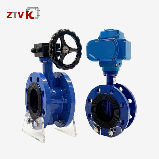
Connecting a water main butterfly valve to piping requires precise alignment and proper sealing to ensure leak-free operation in high-pressure municipal systems. The wafer-type butterfly valve fits between two pipe flanges, secured by through-bolts that compress gaskets against both the valve body and flange faces. Installation begins with inspecting pipe alignment and verifying the valve disc orientation, allowing rotation clearance before tightening bolts in a star pattern to prevent gasket distortion. This quarter-turn valve design streamlines installation compared to multi-turn alternatives, reducing labour costs while maintaining reliable shutoff in water distribution networks.
Understanding the Water Main Butterfly Valve and Its Role
For water distribution systems, valves need to be small and reliable at controlling flow. Butterfly valves work great in these situations. The working concept is based on a disc that is attached to a shaft and turns 90 degrees. The disc goes from fully open (disc parallel to flow) to fully closed (disc perpendicular to flow). Butterfly valves move in a quarter-turn, which is different from gate valves, which need to be rotated more than once and take up a lot more room when installed.
Wafer-Type Design Advantages
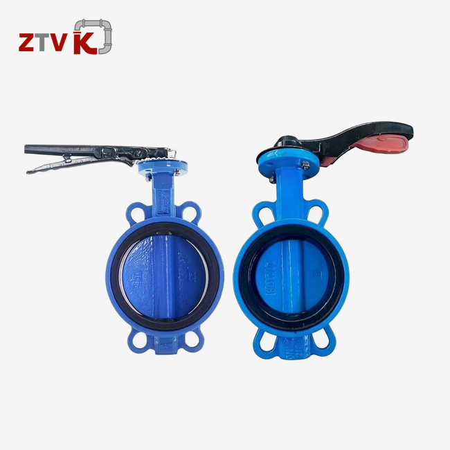
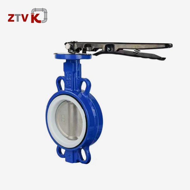
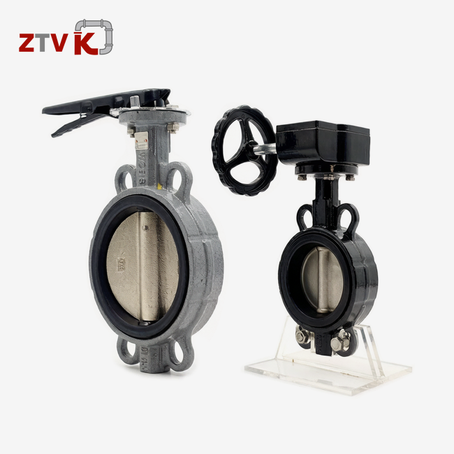
Wafer-type butterfly valves don't need standard flanged valve bodies because they fit right between the flanges on the pipes. Compared to flanged valves, this design cuts weight by about 40%, making it easier to handle during installation in tight areas like underground vaults. The form also cuts down on face-to-face dimensions, which makes it perfect for retrofit jobs where limited room means fewer equipment choices. The specs for making wafer valves usually match the mounting interfaces in ISO 5211, which makes sure that they can work with a wide range of actuators in global supply chains.
Material Selection for Durability
Body materials have a direct effect on how well they resist corrosion and how long they last in buried service environments. When compared to grey cast iron, ductile iron (DI) valve bodies that meet ASTM A536 standards have higher yield strengths of over 45 ksi. The code QT450 means quenched and tempered ductile iron, which provides better protection to impact, which is important for thermal cycling in outdoor setups. Different types of discs are used for different types of applications. For example, ductile iron discs are fine for systems that provide drinking water, while CF8 (304 stainless steel) or CF8M (316 stainless steel) discs can handle chloride-induced rust in coastal areas or wastewater treatment plants.
The closing surface between the disc and the body is made of seat materials. EPDM rubber is used a lot in public water systems because it can handle temperatures from -40°F to 248°F and doesn't react with chlorine. PTFE (polytetrafluoroethylene) handles harsh chemicals, while NBR (nitrile) seats work well with fluids that are based on gasoline. VITON fluoroelastomer seats can handle temperatures up to 400°F, but they are much more expensive. When used with stainless steel stems in saltwater, aluminium bronze discs stop galvanic corrosion.
Pressure Ratings and Size Range
The designations PN10 and PN16 mean pressure ratings of 10 bar (145 psi) and 16 bar (232 psi), which are the same as European standards for water mains in cities. Class 150 ratings (285 psi at room temperature) are often used in North American standards. Sizes range from 1.5 inches to 48 inches (DN40 to DN1200), and they cover everything from home distribution branches to main transmission lines. When compared to gate valves, larger-diameter valves (24 inches and up) save a lot of money because the material costs are usually 60% less per unit.
Preparing for Connection: Tools, Components, and Safety Measures
Installing a valve correctly starts long before the wrench hits the first bolt. Systematic planning keeps expensive repairs from having to be done and makes sure that working conditions in pressurised systems are safe.
Essential Tools and Components
In addition to the water main butterfly valve itself, installation needs certain hardware. Which gasket to use depends on the type of flange. For example, ANSI Class 125/150 flanges need full-face gaskets, while raised-face flanges need ring-type gaskets. It is important that the materials work well together. Compressed asbestos-free (CAF) gaskets work well in high-temperature situations, while EPDM gaskets work well in most situations involving drinkable water. Bolt kits need to have nuts, washers, and through-bolts that are long enough to go through both flanges and the thickness of the valve body. Usually, the lengths need to be 3–4 inches longer than the combined stack height.
For example, torque tools that are tuned to specific bolt sizes keep you from over-tightening, which can damage gaskets, or under-tightening, which can let leaks happen. Socket sets with bolt heads that match (usually hex heads from 3/4 inch to 1-1/4 inch for valves up to 12 inches) make construction easier. When mounting an actuator, you might need extra tools. For example, pneumatic actuators need air line fittings and pressure regulators, and electric actuators need electrical connections and limit switch adjustments.
Pre-Installation Safety Checks
Depressurising the system is the most important safety step. By closing upstream isolation valves and opening drain points, you get rid of any remaining pressure that could push parts during disassembly. Before removing any links, pressure checking with gauges makes sure there is no pressure. Lockout/tagout procedures keep systems from turning back on by accident while workers are on them.
By checking the alignment, you can escape the stress of fitting that hurts valve seats. Straightedges or dial indicators can be used to make sure that the flange sides are parallel to each other within 1/16 inch across the circle. Pipe supports should stop shifting, which causes angles to be out of place. Cleaning the sides of flanges gets rid of rust, old gasket material, and other things that can make closing less effective. Wire brushing and solvent wiping surfaces properly get them ready.
Step-by-Step Guide to Connecting the Water Main Butterfly Valve to the Pipe
Methodical installation sequences stop common mistakes and get the best sealing results. Each step builds on the one before it to make sure the structure is strong and the system works well.
Valve Inspection and Orientation
As you unpack, you'll see protected shipping caps on both ends of the valve. Take these off and check the cleanliness of the opening. Turn the valve disc by hand all the way around to make sure it works smoothly and doesn't get stuck. Although most butterfly valves can work in both directions, make sure that the disc orientation arrow stamped on the body matches the direction of flow that you want. Make sure that the mounting pads for the actuator match the standards for accessing the pipeline. If necessary, rotate the gearbox or actuator before fitting to make sure it fits correctly.
Gasket Placement and Valve Positioning
Make sure the bolt holes are exactly lined up on the downstream flange face and centre the seal there. Some workers like to put gaskets on both sides at the same time to keep them from moving while the valve is being inserted. Move the valve between the flanges. For valves less than 6 inches, one person is usually enough, but for bigger ones, lifting equipment or more than one worker is needed. During installation, the valve disc should rest in the fully open position to reduce the cross-sectional profile and make it easier to fit between the flanges.
Bolt Installation and Tightening Sequence
Put in through-bolts at the same time from the upstream side and thread nuts loosely on the downstream side. Tighten all the bolts by hand before using torque tools. This keeps the seal tension even. Tightening in a star design keeps the gasket from distorting—tighten opposing bolts in small steps instead of fully tightening one bolt before going on to the next. The torque ranges from 30 ft-lbs for 1/2-inch bolts to 150 ft-lbs for 1-inch bolts, depending on the width and material of the bolt. Tighten three times, hitting the final torque values on the third pass after the seals have been compressed and seated properly.
Actuator Installation and Calibration
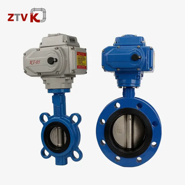
Attaching hand lever operators to the stem of the water main butterfly valve is done directly through ISO 5211 square or double-D drive connections. Set screws and locking mechanisms are used to keep them in place. Worm gear users need the shaft link to be aligned. Misalignment greater than 0.010 inches wears out bearings too quickly. Set the handwheel at a comfortable height for the user, which is usually 3–4 feet above the ground.
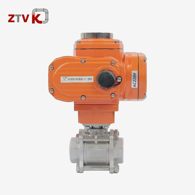
Pneumatic actuators need air supply lines that are regulated to the manufacturer's standards, which are usually between 60 and 80 psi. Check the operation of the solenoid valve and the position of the limit switch to make sure it is fully open and closed. Electric actuators need to be checked for voltages that meet the numbers on the label (120VAC, 240VAC, or 480VAC three-phase). To keep the valve from breaking, set the open and close torque limits a little below the maximum ratings. These limits should be between 80 and 90% of the published values.
Pressure Testing and Operational Verification
Slowly put pressure back into the system while checking all of its connections for leaks. Putting the system under 50% of its working pressure at first lets you find big leaks before the full system pressure is reached. When a soap solution is put on sealed surfaces, pinhole leaks show up as bubbles. Under pressure, open and close the valve several times to make sure it works smoothly and that the disc shuts fully when it's closed. Check the pressures upstream and downstream to make sure the drop stays within acceptable limits, which are usually less than 5 psi for fully open butterfly valves.
Troubleshooting Common Problems During and After Installation
Even with careful placement, problems can sometimes happen. System reliability is maintained, and valve service life is increased by recognising symptoms and taking corrective action.
Leak Detection and Correction
Weeping along flange joints is a common sign of a gasket leak, which is usually caused by not tightening the bolts enough or uneven tension. Re-torque all the bolts in a star pattern, making sure that each one meets the requirements. Leaks that won't stop could mean that the gasket surfaces are broken. This problem can be fixed by taking the machine apart, inspecting the flange face, and replacing the gasket. Stem seal leaks show up as dripping around the shaft while the valve is running. To fix this, tighten the packing nuts a little at a time (usually 1/4 turn at a time) until the leak stops without stopping the valve from running.
Alignment Issues
Too much fitting force could mean that the opening isn't lined up right or that the valve is the wrong size. Take out the valve and measure the pipe flange separation again. Wafer valves need flange gaps that are exactly the same as the valve face-to-face dimension, plus or minus 1/8 inch. Angle misalignment is caused by pipes sliding and can be fixed by shimming or adjusting the supports. When you order valves, make sure they meet the measurements required by ANSI B16.10 or ISO 5752 standards. Valve dimensions that are too big won't fit between flanges, and valve dimensions that are too small will leave bolt length gaps.
Operational Difficulties
Too much working force of a water main butterfly valve is often caused by misalignment of the discs or internal debris. When installing, fully opening the valve keeps the disc from getting in the way of the bolt threads. By flushing the pipeline before installing the last valve, welding slag and other building waste are removed. Actuator failures are caused by incorrect limit switch settings, low air pressure, or voltage mismatches. Differences can be found by comparing manufacturer specifications to actual site conditions. Periodic exercise, like changing valves every three months, keeps the seat from getting hard and keeps the mechanical freedom.
Conclusion
Installing water main butterfly valves correctly requires technical skill and organised planning. This makes sure that key infrastructure systems work reliably. The wafer-type design makes it easier to connect to existing pipelines, and the different materials, from ductile iron bodies to stainless steel discs, can handle a range of environmental conditions. By following structured installation procedures, such as checking the alignment before installation and then testing the pressure after installation, common problems like leaks and operating problems can be avoided. It's helpful for procurement workers to understand the details of specifications and compare valve technologies based on their lifecycle costs instead of just the original purchase price. Strategic source selection gives top priority to makers that offer full expert support, certified materials, and flexible delivery schedules that fit with project deadlines.
FAQ
1. What size butterfly valve do I need for my water main project?
Butterfly valves come in sizes that directly match the standard pipe diameter. For example, a 6-inch pipeline needs a 6-inch valve (DN150). Oversizing makes the flow rough and makes it hard to control, while undersizing raises the pressure drop and flow speed. Check the flow rate estimates and pressure drop charts to make sure that the size you choose keeps the speeds between 5 and 10 feet per second for the best performance in city water systems.
2. How often should water main butterfly valves be exercised?
When valves are in use, they should be exercised every three months by going through full open-close strokes. This keeps the seat from getting hard and keeps the mechanical freedom. Buried valves that are reached through valve boxes need to be inspected and exercised at least once a year. Every six months, emergency isolation valves in important mains should be checked to make sure they are ready to go when they are needed.
3. Can I retrofit an electric actuator onto an existing manual butterfly valve?
Most butterfly valves made to ISO 5211 standards can have actuators added to them without having to change the valve body. Make sure that the current stem's width and the way the mounting pads are set up match the actuator's requirements. In most cases, retrofitting only involves taking off the hand operator and attaching the electric actuator directly to the valve stem. The original valve body and trim parts are kept.
Connect with ZTVK for Your Water Main Butterfly Valve Requirements
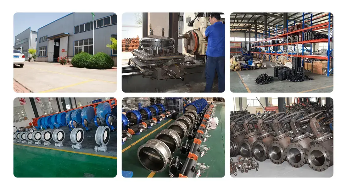
Before you can choose professional valves, you need to know what your system's parameters and operational needs are. Water main butterfly valves from ZTVK are available in sizes ranging from 1.5 inches to 48 inches. They have ductile iron bodies, a choice of seat materials, and meet PN10/PN16 pressure standards. Over 2,000 standard units are kept in stock at our Tianjin plant and can be delivered within 3–7 days. For unique OEM needs, our engineering team supports production cycles of 15–25 days. We serve industrial valve distributors and municipal contractors all over North America and Europe. Our ISO 9001 certification and closeness to Tianjin Port make global shipping quick and easy. Our technical experts can help you with any project, whether you need to buy in bulk for trade or get engineering help for a specific project. They can give you application advice, CAD drawings, and thorough quotes. Get in touch with us at ktec86961886@163.com to talk about your needs with a water main butterfly valve supplier that is dedicated to quality, responsiveness, and competitive pricing that makes your supply chain more reliable.
References
1. American Water Works Association. (2020). AWWA C504 Standard for Rubber-Seated Butterfly Valves. Denver: AWWA Publications.
2. Beerman, D. & Hutchison, R. (2018). Industrial Valve Selection and Maintenance Handbook. Houston: Gulf Professional Publishing.
3. International Organisation for Standardisation. (2019). ISO 5211: Industrial Valves - Part-Turn Actuator Attachments. Geneva: ISO Standards.
4. Lyons, W.C. & Plisga, G.J. (2021). Standard Handbook of Petroleum and Natural Gas Engineering (Third Edition). Oxford: Elsevier Science.
5. Skousen, P.L. (2017). Valve Handbook (Third Edition). New York: McGraw-Hill Education.
6. Zappe, R.W. (2019). Valve Selection Handbook: Engineering Fundamentals for Selecting the Right Valve Design for Every Industrial Flow Application. Burlington: Elsevier Gulf Professional Publishing.
Send us your valve requirements and our team will provide professional solutions and fast quotations.
RELATED INDUSTRY KNOWLEDGE
