- English
- French
- German
- Portuguese
- Spanish
- Russian
- Japanese
- Korean
- Arabic
- Greek
- German
- Turkish
- Italian
- Danish
- Romanian
- Indonesian
- Czech
- Afrikaans
- Swedish
- Polish
- Basque
- Catalan
- Esperanto
- Hindi
- Lao
- Albanian
- Amharic
- Armenian
- Azerbaijani
- Belarusian
- Bengali
- Bosnian
- Bulgarian
- Cebuano
- Chichewa
- Corsican
- Croatian
- Dutch
- Estonian
- Filipino
- Finnish
- Frisian
- Galician
- Georgian
- Gujarati
- Haitian
- Hausa
- Hawaiian
- Hebrew
- Hmong
- Hungarian
- Icelandic
- Igbo
- Javanese
- Kannada
- Kazakh
- Khmer
- Kurdish
- Kyrgyz
- Latin
- Latvian
- Lithuanian
- Luxembou..
- Macedonian
- Malagasy
- Malay
- Malayalam
- Maltese
- Maori
- Marathi
- Mongolian
- Burmese
- Nepali
- Norwegian
- Pashto
- Persian
- Punjabi
- Serbian
- Sesotho
- Sinhala
- Slovak
- Slovenian
- Somali
- Samoan
- Scots Gaelic
- Shona
- Sindhi
- Sundanese
- Swahili
- Tajik
- Tamil
- Telugu
- Thai
- Ukrainian
- Urdu
- Uzbek
- Vietnamese
- Welsh
- Xhosa
- Yiddish
- Yoruba
- Zulu
Composition and Working Principle of Electric Actuator
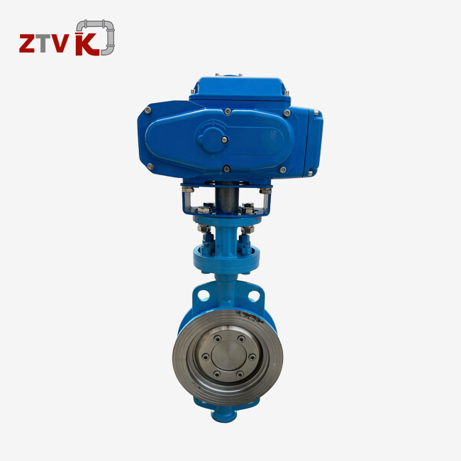
When industrial processes demand precise, automated control over large-diameter pipelines, the butterfly valve motorized actuator emerges as the critical component linking electrical command signals to mechanical motion. This electromechanical device integrates an electric motor with sophisticated gearing and control electronics to rotate a butterfly valve disc through a 90-degree arc, regulating fluid flow with exceptional accuracy. Unlike manual handles or gear operators that require physical presence and considerable effort, motorized actuators enable remote operation from control rooms, eliminating safety risks in hazardous environments and ensuring consistent performance across thousands of operating cycles. Understanding how these devices are built and how they function empowers procurement professionals to make informed decisions that optimize system reliability and operational efficiency.
Understanding the Composition of Electric Actuators for Butterfly Valves
A butterfly valve motorized actuator is made up of several linked parts, each of which does a different job in turning electrical energy into controlled rotational movement. Buyers can judge the quality of the build and how well it works with their current systems by seeing what's inside.
Core Motor Assembly
The main part is a brushless or brushed DC/AC motor, which is chosen based on the duty cycle needs and the power source that is available. Industrial setups usually use AC220V and AC380V configurations because they work with the power grid. DC designs are better for situations where you need a backup battery. The motor creates the initial spinning force, and the insulation on the windings is rated to handle high and low temperatures as well as electrical stress from starting and stopping the motor many times.
Gearbox and Torque Transmission
The raw motor speed is usually between 1,200 and 1,800 RPM, which is much faster than what the valve needs to work. Either a worm-and-wheel or planetary reduction gearbox slows down the speed while increasing the power. Worm gears have self-locking features that stop them from backdriving under pressure, while planetary designs are smaller and work more efficiently. When properly oiled, gears made of hardened steel or bronze don't wear out as quickly, so they can last longer than 50,000 rounds before they need to be serviced again.
Control Electronics and Signal Processing
Printed circuit boards inside modern actuators read incoming data and act on it. Simple voltage commands tell on/off models to open or close valves to their fullest open or closed positions. Modulating types can work with either 4-20 mA or 0-10 V analog signals, pausing in between to precisely control the flow. More advanced units can communicate with digital standards like Modbus RTU or Profibus and send diagnostic data to control systems, such as torque curves and cycle counts.
Position Feedback Mechanisms
Control systems are always getting shaft angle information from potentiometers, encoders, or Hall effect sensors. This closed-loop feedback makes sure that the valves stay in the right place even if the load changes or there is mechanical resistance. When purchasing things, teams look for actuators with two types of feedback to make sure that if one sensor fails, it won't mess up the process.
Environmental Protection Housing
IP67 or IP68 enclosures protect the inside from dust and short-term submersion, which is very important in water treatment plants or outdoor sites. Coatings that don't rust, like epoxy resin for humid areas and C4 marine-grade paint for coastal areas, make things last longer in harsh environments. Weatherproof cable glands stop water from moving along wiring lines, which is a common way for things to go wrong that is missed when setups are rushed.
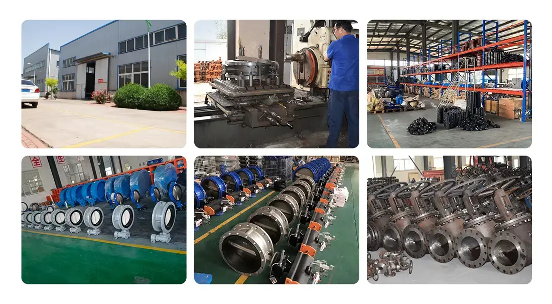
When contractors and distributors know about these building blocks, they can tell if a supplier has spent money on high-quality parts or saved money by using cheap materials. ZTVK uses ISO9001-certified methods to put these parts together, making sure that every actuator that leaves our Tianjin plant meets high-performance standards.
Working Principle of Electric (Motorized) Actuators in Butterfly Valves
Through a series of coordinated steps, the operational sequence turns electrical commands into the movement of a mechanical valve. Each step depends on exact timing and force management.
Power Application and Motor Activation
Electromagnetic fields make the motor spin when a control signal turns on the windings. Regulatory models see analog current levels as position goals, while switch-type motors get binary commands—voltage on for open and off for closed—in a butterfly valve motorized actuator. Internal contacts or solid-state switches handle reversing the polarity, which lets the motor turn in both directions. Thermal overload protection checks the temperature of the windings and cuts the power off if too much heat threatens the insulation.
Torque Multiplication and Shaft Coupling
The output of the motor goes into the input shaft of the gearbox. There, gear trains slow down the motor and increase its torque based on the design ratios. A 1:60 ratio changes 1,800 RPM into 30 RPM power, and it also increases torque from 0.5 Nm to 30 Nm. The output flange is moved by this increased force, and it is connected to the valve stem by an ISO5211 standard coupling. When you line things correctly, you stop side loading, which wears down bearings faster and causes positional mistakes.
Valve Disc Rotation and Flow Control
The butterfly disc inside the valve body moves as the stem turns. The disc slowly moves off its seat, making a crescent-shaped flow passage, starting from a closed position. At 30 degrees, the flow is about half of its maximum, and at 70 degrees, turbulence is at its lowest, which makes the pressure drop characteristics best. A full 90-degree hole allows the least amount of restriction and matches the width of the pipeline. Compared to concentric designs, double-eccentric designs have less seat friction during this motion, which means that 30% less actuator force is needed.
Position Feedback and Control Loop Closure
As the stem rotates, feedback devices send real-time position data. In modulating mode, the controller checks the real position against the setpoint and changes the motor power to fix any mistakes. Proportional-integral-derivative (PID) methods stop oscillations and keep the position fixed within ±1 degree. Limit switches stop motion at the ends of a travel path, which prevents mechanical damage from happening from turning too fast. This closed-loop architecture makes precise flow control possible, which is important for dosing systems for water treatment and optimizing HVAC energy use.
Fail-Safe Operation During Power Loss
When the power goes out, critical safety applications demand predictable behavior. Standard motors stop moving when they reach their final position, which keeps the flow going. Battery-powered units use stored charge to keep controlled movement going until they reach a safe state. When the power goes out, spring-return systems use compressed coil springs that open up, forcing valves shut and isolating dangerous fluids. Process safety analysis is needed to choose the right fail mode, which can be freeze, fail-open, or fail-closed. Contractors must be clear about this choice during the specification phases.
This working principle shows why electric actuators are the most common choice for industrial uses that need to be controlled remotely, integrate automation, and be reliable without any upkeep.
Comparison of Electric Motorized Actuators with Other Actuator Types
Choosing between electric, pneumatic, and manual actuation involves weighing performance advantages against cost and infrastructure constraints. Each technology occupies distinct niches based on application demands.
Electric butterfly valve motorized actuators work best in automation settings that already have electrical wiring in place. They get rid of the need for compressed air systems, which saves energy and makes it easier to set up pipes. Precision pointing solves flow control problems in HVAC zones and chemical dosing loops, where air motors have trouble with drift and hysteresis. The initial costs are 40–60% higher than with manual gearboxes, but the labor savings from being able to operate and diagnose remotely pay for the system within two years for installations that get a lot of use.
Since electric sparks can start fires, pneumatic valves are still the best choice in areas that are likely to explode and need fundamentally safe designs. Air-driven units have fast stroking speeds that are good for emergency shutdowns, but they are vulnerable because they depend on the air compressor being up and running all the time. Filter-regulator-lubricator (FRL) parts need to be serviced every three months, which makes maintenance more difficult compared to electric motors, which are sealed and don't need any maintenance. A butterfly valve motorized actuator provides an electric solution for valve automation where reliable and low-maintenance operation is required.
Because they cost 70% less than powered options, manual operators are good for low-frequency tasks and projects with limited funds. But contractors are moving toward automation because it's harder to get to sites that are above or below ground and because large-diameter valves larger than DN600 can be dangerous for workers' health. Turning handwheels on 12-inch butterfly valves over and over again can cause injuries on the job, which is one reason why electric solutions are being used more.
Brand comparisons reveal quality differentials impacting total cost of ownership. Siemens focuses on industrial robustness with certifications for hazardous areas, while Belimo focuses on HVAC features like spring-return and two-position control. Honeywell makes building control easier by combining the BACnet and LonWorks technologies. ZTVK is in the middle of the premium and mid-tier segments. It meets international standards for mounting and is certified by EN and ISO5211. It also comes with 18-month warranties and quick technical support, which makes it a good deal for distributors who serve price-conscious markets without sacrificing quality.
Installation, Maintenance, and Troubleshooting of Motorized Butterfly Valve Actuators
The lifespan and downtime of an actuator are directly affected by how well it is installed and maintained. By following structured processes, you can avoid common mistakes that lead to failures before they happen.
Installation Best Practices
The first step in mounting is to make sure that the valve stems are compatible. ISO5211 flanges make mechanical interfaces the same, but the stem height and key size are not. When there is misalignment, bent loads are introduced, which break gear teeth within 5,000 cycles. Mounting bolts won't come loose when they're tightened to the specified torque. According to NEC or IEC guidelines, electrical connections need to be grounded, have the right voltage grade, and match the phases. Control wiring should use shielded wires to keep power and signal lines separate. This will keep electromagnetic interference from messing up analog signals as little as possible. As part of the initial commissioning process, the jog is tested by hand to make sure it works in the right direction. This is followed by calibration, which sets the travel limits and feedback zero points.
Preventive Maintenance Protocols
Every six months, the structure of the house is checked for cracks that let water in. The frequency of operation determines how often the gearbox needs to be greased. For continuous modulating duty, lithium-based EP compounds need to be used once a year. Seal state checks keep water from getting into PCBs and breaking them down. Recalibrating the potentiometer fixes any drift caused by wear and restores the accuracy of the position. By keeping track of cycle counts, predictive replacement can be done before a catastrophic failure stops operations. Extreme temperatures or corrosive atmospheres speed up decline, which is why reviews should be done every three months in petroleum plants instead of every two years in HVAC settings that are generally safe.
Common Troubleshooting Scenarios
When motors don't work, it's often because fuses or circuit breakers have blown, which is easy to miss when you're in a hurry to find the problem. Checking the supply voltage at the motor ports separates problems with the power source from mechanical jams. If there are feedback errors that show incorrect positions, it means that the potentiometer is broken or the wiring is disconnected. Switching the signal wires between units can tell the difference between component and controller flaws. When waterproofing fails, things act strangely or stop working completely after it rains. Checking the tightness of the cable glands and the drainage of the conduit stops this from happening again. Gear wear causes grinding sounds and draws more power. Measuring torque under load figures out how bad the wear is, which tells you when to replace the gear. Using multimeters, torque wrenches, and maker diagnosis software in a planned way speeds up the resolution process and lowers the cost of downtime.
Contractors appreciate it when providers give them thorough installation guides and flowcharts for fixing problems. ZTVK provides video instructions and bilingual documentation that talk about the real problems that field technicians face when they are commissioning and fixing things in an emergency with a butterfly valve motorized actuator.
Conclusion
Learning about the parts of electric motors and how they work turns choosing valves from a guessing game into a smart decision-making process. These machines are the foundation of modern industrial automation because they combine precise electrical control with mechanical dependability. Procurement workers can easily recommend solutions that meet operational needs when they understand motor dynamics, gearbox mechanics, and control integration. When you compare it to gas and manual options, you can see the pros and cons of each. You can also learn how to install and maintain it so that it works well for a long time. Structured selection frameworks make sure that technical, commercial, and legal factors are all taken into account so that partnerships with suppliers really add value. With this information, distributors, contractors, and end users can improve the safety, efficiency, and profits of fluid control systems in the petrochemical, municipal infrastructure, water treatment, and HVAC industries.
FAQ
1. How do motorized actuators enhance valve performance compared to manual operation?
Motorized actuators get rid of the need for manual labor and allow direct control from centralized systems, which speeds up emergency reaction times. Flow throttling, which can't be done with handwheels, can be supported by precise placement within one degree. Integration with PLCs and DCS makes automated routines easier, which improves process accuracy and frees up workers to do more important work.
2. What are the usual shipping times and wait times for large orders?
If you order fewer than 50 standard models, they will ship within 3–7 business days from when they are in stock. Depending on how complicated they are, custom configurations take 15 to 25 days. Because ZTVK is close to Tianjin Port, it can use FOB or CIF terms for consolidated ocean freight, which lowers the cost of logistics. Urgent needs can be met by air freight, but there are extra fees.
3. What troubleshooting steps resolve common actuator issues quickly?
First, check the voltage of the power source and the state of the circuit breakers. Check the links between the cables for rust or looseness. Use multimeters to look at return signals and find sensor problems. When there are problems with the valves, mechanical resistance shows up as high motor power draw. For specific fixes, look at the manufacturer's diagnostic codes that are shown on control panels.
Partner with ZTVK for Reliable Butterfly Valve Motorized Actuator Solutions.
ZTVK is ready to help you with your valve control needs. They can make a wide range of products because they have been making things in Tianjin for more than 15 years. Our qualifications as a butterfly valve motorized actuator provider include ISO9001 quality systems, a large inventory that allows standard fulfillment in 3–7 days, and open OEM/ODM customization that can solve specific application problems. Whether you need ductile iron bodies for municipal waterworks or stainless steel 316 configurations for corrosive petrochemical environments, our engineering team can help you make the right choice to protect the environment and get the best torque matching. Distributors who manage regional stocks can benefit from bulk price structures. Responsive technical support, such as installation videos and troubleshooting help, lowers the risks of your project. You can email our team at ktec86961886@163.com to talk about your needs, ask for CAD drawings, or get competitive quotes with 18-month warranties.
References
1. National Fluid Power Association (2021). "Actuator Technologies in Industrial Automation Systems," NFPA Technical Standards Journal, Vol. 45, pp. 112-134.
2. Wright, P. & Miller, D. (2020). "Electric Actuators: Design, Selection, and Application," Industrial Press Inc., New York, 3rd Edition.
3. International Society of Automation (2019). "Control Valve Actuator Sizing and Performance Standards," ISA-75.25.01 Technical Report.
4. Chen, L. & Robertson, K. (2022). "Comparative Analysis of Actuation Technologies for Quarter-Turn Valves," Journal of Process Control Engineering, Vol. 38, No. 2, pp. 45-67.
5. European Committee for Standardization (2018). "Industrial Valves – Part-Turn Actuator Attachments," EN ISO 5211:2018 Standard Documentation.
6. Hutchison, R. (2020). "Maintenance Best Practices for Motorized Valve Actuators in Water Treatment Facilities," Water & Wastewater International, Vol. 35, Issue 4, pp. 22-29.
Send us your valve requirements and our team will provide professional solutions and fast quotations.
RELATED INDUSTRY KNOWLEDGE
