- English
- French
- German
- Portuguese
- Spanish
- Russian
- Japanese
- Korean
- Arabic
- Greek
- German
- Turkish
- Italian
- Danish
- Romanian
- Indonesian
- Czech
- Afrikaans
- Swedish
- Polish
- Basque
- Catalan
- Esperanto
- Hindi
- Lao
- Albanian
- Amharic
- Armenian
- Azerbaijani
- Belarusian
- Bengali
- Bosnian
- Bulgarian
- Cebuano
- Chichewa
- Corsican
- Croatian
- Dutch
- Estonian
- Filipino
- Finnish
- Frisian
- Galician
- Georgian
- Gujarati
- Haitian
- Hausa
- Hawaiian
- Hebrew
- Hmong
- Hungarian
- Icelandic
- Igbo
- Javanese
- Kannada
- Kazakh
- Khmer
- Kurdish
- Kyrgyz
- Latin
- Latvian
- Lithuanian
- Luxembou..
- Macedonian
- Malagasy
- Malay
- Malayalam
- Maltese
- Maori
- Marathi
- Mongolian
- Burmese
- Nepali
- Norwegian
- Pashto
- Persian
- Punjabi
- Serbian
- Sesotho
- Sinhala
- Slovak
- Slovenian
- Somali
- Samoan
- Scots Gaelic
- Shona
- Sindhi
- Sundanese
- Swahili
- Tajik
- Tamil
- Telugu
- Thai
- Ukrainian
- Urdu
- Uzbek
- Vietnamese
- Welsh
- Xhosa
- Yiddish
- Yoruba
- Zulu
How to disassemble an actuator-operated butterfly valve?
Disassembling an actuator-operated butterfly valve involves systematically isolating power sources, disconnecting the actuator from the valve body, and carefully removing internal components like the disc, shaft, and seals. This maintenance procedure ensures optimal performance, extends service life, and prevents unexpected system failures. Proper disassembly requires understanding the valve's construction—where a quarter-turn disc controls flow—and recognizing that pneumatic or electric actuators add complexity requiring specialized attention to wiring, air lines, and mounting interfaces compliant with ISO 5211 standards.
Understanding the Actuator-Operated Butterfly Valve Before Disassembly
Core Components and Their Functions
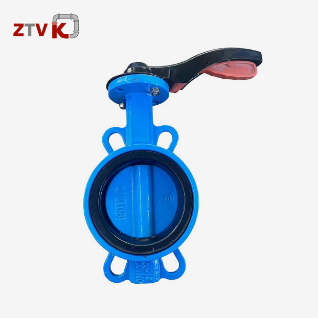
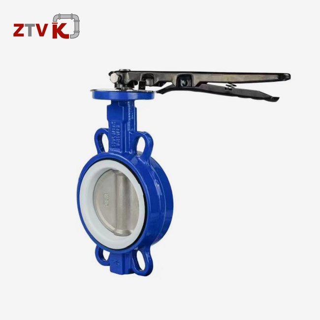
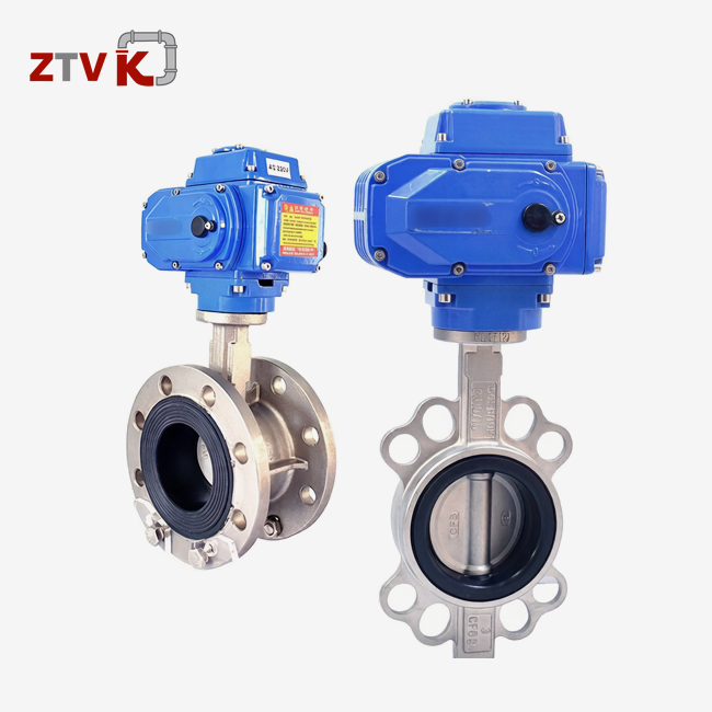
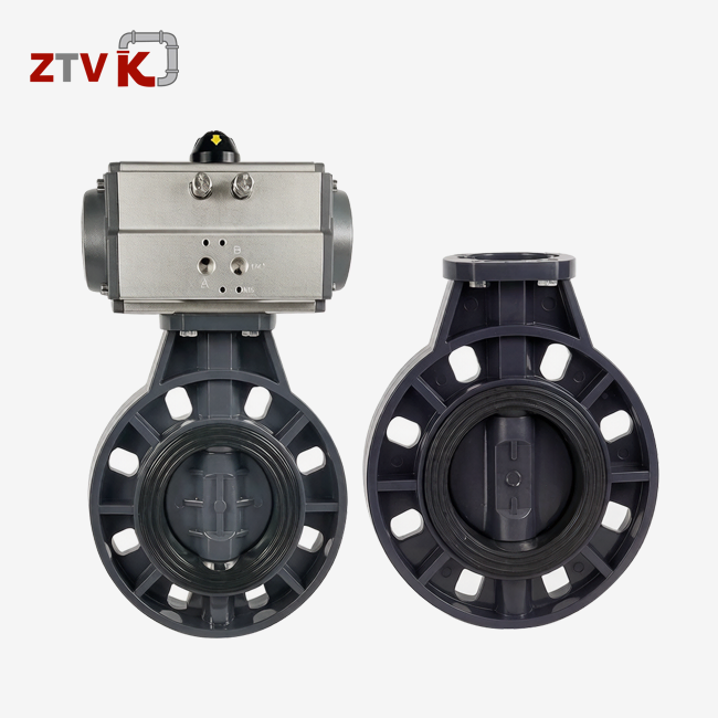
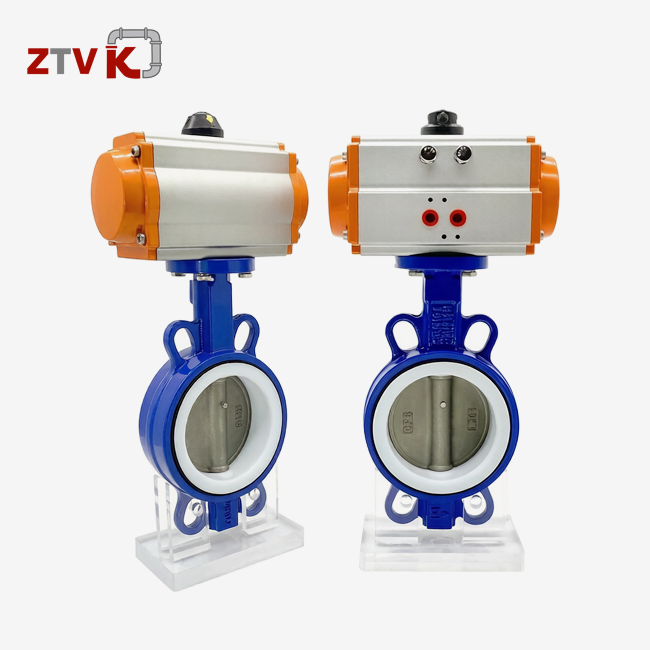
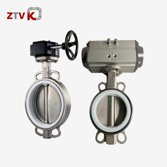
A ductile iron (DI), CF8, CF8M, or WCB cast steel valve body carries a revolving disc on a stainless steel shaft (grades SS304, SS316, or SS410/416, depending on corrosion resistance). Turn the disc 90 degrees to close it. For sealing, EPDM, Nitrile, VITON, or PTFE seats are employed. Material selection depends on fluid chemistry and temperature. Rack-and-pinion systems convert pressurised air into rotary force in the actuator. It can be single-acting with spring return or double-acting pneumatic with hard-anodized aluminium. Instead of pneumatic sources, electric models use motors and gearing systems powered by electrical connections.
Recognizing Design Variations
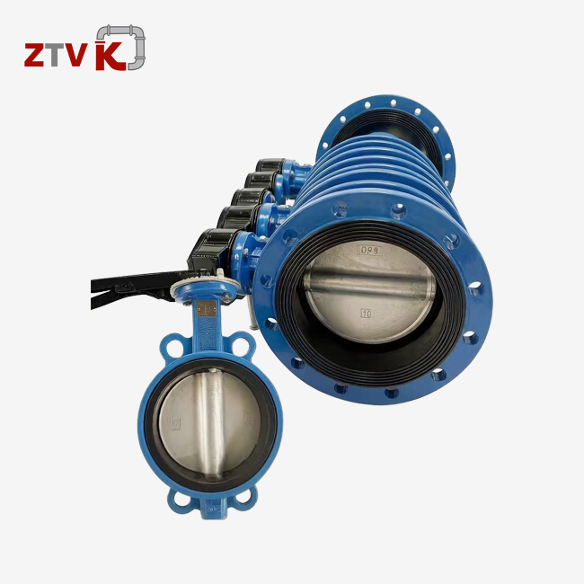
Without bolt holes, wafer-type valves are placed between flanges. Through-bolts hold them in place, making removal easier but requiring pipeline handling. ASME B16.5 flanged-end types (150 or 300 pressure classes) bolt directly to mating flanges, making them easier to remove. The force needed to reassemble your system depends on whether it employs PN10 or PN16 pressure levels. Actuators and valves are straightforward to replace thanks to the ISO 5211 mounting interface. OEM clients who incorporate valves in custom machines and need to increase automation without replacing assemblies will benefit from this.
Why Maintenance Matters
Conditions of operation that are too harsh speed up component wear. In chemical processing settings, aggressive media can weaken seals, and abrasive slurries in urban sewer systems can wear down disc surfaces. Opening and closing thousands of times a month in automated control loops causes shaft bearings to wear out and mounting hardware to come loose. If you don't do your regular maintenance, small seal leaks can turn into full system shutdowns, which means you have to buy new parts quickly at a higher cost. Distributors who serve regional markets know that selling products and providing maintenance advice at the same time keeps customers coming back and brings in repeat business through technical service contracts and spare parts supply.
Preparing for Safe and Effective Disassembly
Gathering Necessary Tools and Equipment
To disassemble something properly, you need socket sets for both metric and imperial sizes, adjustable wrenches that are the right size for actuator mounting bolts, precision torque wrenches that are calibrated to the manufacturer's specs, and flathead screwdrivers for electrical terminal blocks. Some specialised tools are bearing pullers, which remove shaft bearings without damaging them, brass drift cuts, which don't damage stainless steel surfaces, and number indicators, which check shaft runout during inspection. When working with valves that are exposed to corrosive fluids, you must wear chemical-resistant gloves, safety glasses to protect your eyes from compressed air releases, and steel-toed boots to protect your feet from falling parts. When procurement teams list repair skills, they should make sure that service providers keep stocks of calibrated tools that meet international standards.
Implementing Critical Safety Protocols
The most important safety step for an actuator-operated butterfly valve is to depressurise the system. Use gauges to make sure there is no pressure before loosening any connections. For pneumatic devices, the air supply lines must be cut off, and any remaining pressure must be bled through vent holes. Electric actuators need lockout/tagout processes, which are when trained electricians turn off the power, tag the breaker switches, and use multimeters to make sure there is no voltage. Some installations use electronic positioners with capacitors that store energy and need to be discharged in a certain way, which is explained in the manufacturer's manual. Fluid media hazards are very different. Water systems don't pose much of a threat, but hydrocarbon pipelines or chemical process lines may contain dangerous, flammable, or high-temperature substances that need to be contained and disposed of in a certain way in order to meet environmental regulations.
Documentation and Preparation
Before you start working, take pictures of the valve assembly from different points to show where the actuator is positioned, where the electrical wires go, and how the air tubes are connected. Write down the information on the nameplate, such as serial numbers, pressure ratings, and material specifications. This is important information for ordering replacement parts from suppliers. Check the installation and maintenance guide from the maker. ZTVK products come with full CAD plans and exploded-view diagrams that can be accessed instantly by scanning the QR codes on the nameplates. Write down the original pressure settings on the mounting bolts and keep track of the measures for the shaft's alignment. This paperwork speeds up the reassembly process, makes sure that quality checks can be done in ISO-certified facilities, and gives reference data for figuring out whether parts meet the requirements for continued service or need to be replaced.
Step-by-Step Guide to Disassembling an Actuator-Operated Butterfly Valve
Disconnecting and Removing the Actuator
First, disconnect actuator type-specific control connections. Close pneumatic unit air supply isolation valves and carefully remove compression fittings or quick-connect couplings to release trapped air. Open the junction box, photograph wire connections, detach power cables, and label terminals for electric actuators. Remove limit switches, solenoid valves, and positioner modules and store mounting parts separately.
Four bolts on the actuator base mount it through an ISO 5211 driving interface. Allow penetrating oil to act on corrosion before removing. Cross-loosen bolts to avoid uneven stress. To remove the actuator from the valve shaft, lift it vertically and rotate the coupling slightly. Keep the actuator on a clean surface to avoid drive interface contamination.
Unbolting the Valve from the Pipeline
For wafer-style valves, record the installation direction before removal. Gradually loosen flange bolts in a star pattern to avoid damaging the valve body or flanges. Use properly rated lifting equipment for heavier valves, as large units may exceed 50 kilograms. After removing the bolts, carefully separate the valve from the pipeline.
Flanged-end valves can usually be removed without disturbing nearby pipes. Use wooden wedges to separate the valve from the flange while protecting sealing surfaces. Remove stuck gasket materials with non-metal tools to avoid scratches. Transfer the valve to a repair area using a padded cart to prevent damage to the disc or shaft alignment.
Dismantling Internal Components
Secure the valve body and inspect internal connections. The shaft is supported by bearings or bushings, while gland nuts hold packing or shaft seals to prevent leakage. Remove these components carefully, especially if previous over-tightening has damaged the threads.
Disconnect the disc from the shaft by removing pins, set screws, or keyed connections, depending on the design. Slide the disc off carefully and inspect it for erosion, cavitation, deformation, or other damage. Remove shaft seals with proper tools and record their installation direction and depth.
Use brass punches and a soft-face hammer to remove the shaft without damaging precision surfaces. Press-fit bearings may require pullers or hydraulic presses. Avoid damaging stainless steel shafts or rubber seats during removal, as surface damage can affect sealing performance.
Inspection and Cleaning Procedures
Clean components with suitable solutions: mild detergents for elastomers, isopropyl alcohol for metal parts, and specialized degreasers for oil contamination. Avoid petroleum-based cleaners on EPDM or Nitrile seals, as they can cause swelling and premature failure.
Inspect the valve body for corrosion, pitting, or scratches. Measure shaft diameters at bearing contact points and compare results with manufacturer specifications. Excessive wear can cause shaft movement and early seal failure. Check disc sealing surfaces for scratches, debris, or damage that may prevent complete shutoff.
Inspect seat grooves for cracks, hardening, or loss of elasticity, and check bearings for discoloration caused by poor lubrication or contamination. Record measurements and photos to track component condition and support future spare-part decisions based on actual wear patterns.
Troubleshooting Common Issues During Disassembly
Addressing Seized or Corroded Fasteners
When kept outside or in corrosive situations, actuator mounting bolts and gland nuts on an actuator-operated butterfly valve freeze due to their differing metals. Molybdenum disulphide-based penetrating oils outperform standard lubricants. It should be used liberally and soaked overnight for extreme instances. Metal expands when heated slowly with heat guns (avoid open flames near flammable leftovers), breaking rust bonds. The temperature restrictions of neighbouring elastomeric parts limit this procedure.
Impact drivers generate short bursts of quick spin that break static friction without rounding bolt heads. If fasteners won't come off, carefully grind the threads and drill off any residual fragments. Retap the holes to the original specs. In the Middle East, where high temperatures and dust accelerate rust, ZTVK engineers have developed anti-seize compound application instructions. These guidelines lengthen maintenance and simplify disassembly. These regional adjustments demonstrate how manufacturing knowledge might improve distributor operations in specific climates.
Resolving Actuator Coupling Alignment Problems
ISO 5211 drive interfaces require shaft engagement with hundredths of millimetre accuracy to send the proper torque. Corrosion, dried oils, and filth in keyways or spline teeth prevent smooth actuator removal. Flooding the contact with spray penetrants and carefully rocking the actuator loosens binding. To avoid damaging aluminium actuator housings, use wooden blocks to spread screwdriver pressure.
Last fitting misalignment may have caused uneven wear. Check drive shafts for rounded edges, twisted splines, or extended keyways that indicate overpowering. If you encounter any of these issues, replace the shaft before reassembling. Coupler adapters can loosen when connecting two types of actuators; thus, it's advisable to replace them rather than fix them in the field. Root cause analysis may reveal that the actuators are the wrong size, forcing parts past their design limits and producing coupling problems with several valves. This must be considered while buying to ensure specifications are satisfied.
Managing Shaft and Bearing Extraction Challenges
For shafts that have rusted into body bearings, apply pressure gently and cautiously to avoid cracking the cast iron bodies or bending the shafts. Pressure gauges measure hydraulic bearing pullers' controlled force to prevent overloading. Dry ice on shaft ends shrinks diameters enough to break interference fittings. Temperature limits valve body expansion when bearing heaters warm them due to flexible seats.
Bearing races can break into fragments that get lodged in body bores when removed. Magnetic retrievers stretch to capture metal items, while sticky putty on rod ends grabs non-magnetic pieces. Skilled machine shops with valve body fittings that straighten bearing bores should machine or sleeve damaged bores. Procurement managers should network with speciality repair shops. This is crucial when they manage a fleet of large-diameter valves, as replacing them costs more than reconditioning them.
Post-Disassembly Recommendations and Next Steps
Component Evaluation and Replacement Decisions
Seals and gaskets, bearings and bushings, shafts and discs, and fasteners should be sorted by function. Compare shaft diameter, disc thickness, and seat compression depth to original specs. Surface finish examination shows if roughness exceeds sealing criteria, while hardness or chemical analysis verifies that the right materials and alloys were utilised for maintenance.
Elastomeric seals degrade even when unused. EPDM hardens, Nitrile cracks, and VITON surfaces stick. All seals should be replaced regardless of appearance for valves over the recommended service life—5–7 years for water applications or 2–3 years for chemical applications. Bearings with rough rotation, discolouration, or excessive clearance should be replaced since partial failure might release metal particles and exacerbate seal degradation.
OEM parts have certified dimensions, materials, and performance. ZTVK stocks standard model seal kits, bearing sets, and shaft assemblies. The Tianjin facility, 50 km from Xingang Port, ships in 3–7 days, while special designs take 15–25. Aftermarket parts may save money, but procurement teams should evaluate hazards including improper materials, inadequate tolerances, and missing quality documentation, especially for critical infrastructure applications.
Reassembly Best Practices
Clean reassembly prevents contamination failures. Install seals with lint-free wipes, clean surfaces, and manufacturer-recommended lubricants. Silicone grease works for EPDM, petroleum jelly for Nitrile, and fluorinated grease for VITON. Lubrication lowers installation friction, seal damage, and service life.
To place shaft seals accurately, use the right seal driver. Improvised tools may misalign and leak immediately. Avoid gasket overcompression by using calibrated torque wrenches and cross-pattern tightening. Before restoring the actuator, make sure the disc rotates smoothly over its range to align and remove debris.
For smooth drive engagement, mount the actuator carefully. Installation records require wiring and pneumatic line reconnections. Before applying maximum pressure, manually cycle the valve several times to check operation and limit switch positions. Pressure test at 110% of maximum working pressure per API 598 and check all joints for leaks.
Finally, record valve serial numbers, installed part numbers, torque values, and test results for maintenance. Quality control, traceability, and maintenance history for service planning are supported by these records.
Conclusion
Methodical disassembly of actuator-operated butterfly valves safeguards valuable assets while enhancing technical proficiency necessary for procurement teams, maintenance contractors, and engineering firms managing industrial fluid control systems. The steps described—from carefully preparing the parts to checking them out and putting them back together—are based on tried-and-true methods learned over many years of manufacturing experience and working on projects around the world. By understanding these processes, you can make smart choices about which service provider to hire, how to manage your spare parts inventory, and how to plan the lifecycle of your equipment. When used with high-quality parts that meet international standards and proper maintenance, valves can last for more than 50,000 cycles. Companies that engage in written processes and trained workers have less unplanned downtime, lower upkeep costs, and more reliable operations in places like chemical processing plants, water treatment plants, and energy infrastructure installations.
FAQ
1. How Often Should We Disassemble Valves for Inspection?
How often you inspect depends on how the media is used and how it works. When used normally, water service valves need to be checked every three to five years. In chemical applications, on the other hand, they need to be checked every year because aggressive fluids can damage the seals. High-cycle mechanical systems work better when they are checked every six months to see how they are wearing. Manufacturer instructions give you a starting point for what to do. These can be changed based on your practical experience and the failure modes that are specific to your application. Setting up predictive maintenance plans based on past data helps find the best times for inspections, which stops failures and saves money on labour costs for taking things apart that don't need to be.
2. Can We Use Standard Tools or Are Specialized Implements Required?
Common mechanic's tools, like socket sets, wrenches, and screwdrivers, are used for basic disassembly. For bearing release, precise measurement, and shaft line confirmation, you need special tools. For correct fastener loading during reassembly, torque tools need to be adjusted. Dial gauges find the shaft's runout, which is very important for good fitting. Bearing pullers keep parts from breaking when they are being taken off. Maintenance companies that do regular work buy a lot of different tools. For one-time service jobs, you might need to rent specific tools or hire trained workers who have the right tools and training.
3. What Distinguishes Pneumatic from Electric Actuator Disassembly?
For pneumatic units, you have to cut off the compressed air sources and let the pressure out before you can unhook the tubing. Electric models need lockout/tagout processes to keep the electricity off and careful wire documentation. Mechanically, both types use ISO 5211 mounting interfaces, which make it easier to separate them from the valve bodies. Pneumatic actuators with spring-return systems have primed springs that need to be controlled to release during maintenance. If they are taken apart incorrectly, they could cause harm. Electric motor housings keep sensitive electronics and wiring from getting wet, so they need to be handled carefully during maintenance tasks to keep their ingress protection ratings.
Partner with ZTVK for Reliable Actuator Operated Butterfly Valve Solutions
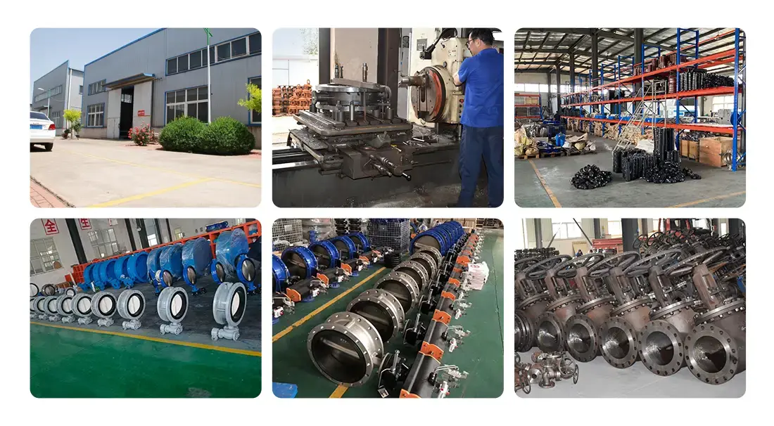
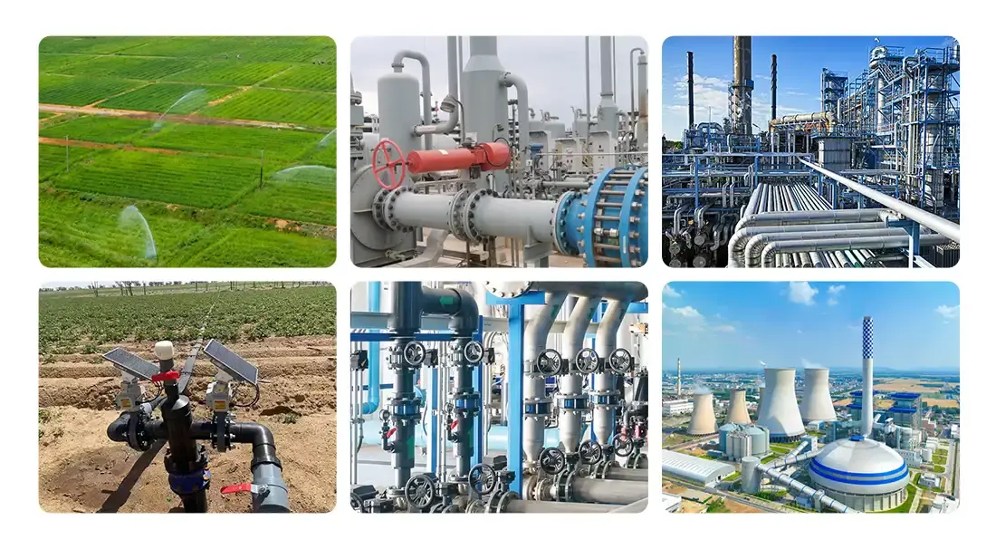
With more than 15 years of experience making specialised products in Tianjin's industrial core, ZTVK is ready to help you with your valve maintenance and purchase needs. We deliver goods that meet API, ANSI, DIN, and CE standards and are perfect for city water systems, petrochemical plants, and HVAC uses all over the world as an actuator-operated butterfly valve provider with ISO9001, ISO14001, and OHSAS18001 certifications. Our two-eccentric oblique seal design lowers operating torque by 30% and achieves a 50,000-cycle service life by using the best materials, such as ductile iron bodies, stainless steel shafts (SS304/316), and application-matched seats (EPDM, VITON, PTFE) that are resistant to a wide range of media. Take advantage of our closeness to the port; shipping from the plant to Xingang can be done in just one hour, allowing us to quickly fill your orders. Standard models (DN50–DN600) ship in 3–7 days from an inventory of more than 2,000 units. Custom OEM solutions that include your brand and unique needs finish production in 15 to 25 days. For help with applications, CAD models, and quotes that are tailored to the needs of a dealer or a particular project, please email our technical team at ktec86961886@163.com. We offer 18-month warranties, installation videos, and technical help, all backed by certifications that can be checked by a third party. This combines the speed of the Chinese supply chain with global quality standards.
References
1. American Petroleum Institute. "API Standard 609: Butterfly Valves—Double Flanged, Lug- and Wafer-Type." Tenth Edition, 2017.
2. International Organization for Standardization. "ISO 5211:2001—Industrial Valves—Part-Turn Actuator Attachments." Geneva, Switzerland, 2001.
3. Skousen, Philip L. "Valve Handbook." Third Edition, McGraw-Hill Professional, New York, 2011.
4. ASME International. "ASME B16.5—Pipe Flanges and Flanged Fittings: NPS 1/2 through NPS 24 Metric/Inch Standard." American Society of Mechanical Engineers, 2020.
5. British Standards Institution. "BS EN 593:2009—Industrial Valves—Metallic Butterfly Valves for General Purposes." London, United Kingdom, 2009.
6. Zappe, R. W. "Valve Selection Handbook: Engineering Fundamentals for Selecting the Right Valve Design for Every Industrial Flow Application." Fifth Edition, Gulf Professional Publishing, Houston, Texas, 2004.
Send us your valve requirements and our team will provide professional solutions and fast quotations.
RELATED INDUSTRY KNOWLEDGE
